
SDOF - Frequency Response Functions
In previous posts, the Displacement Amplification Factor (DAF) was used to understand how to minimize the oscillation of the suspended mass of an SDOF system subjected to forced vibrations.
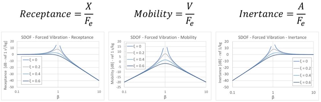
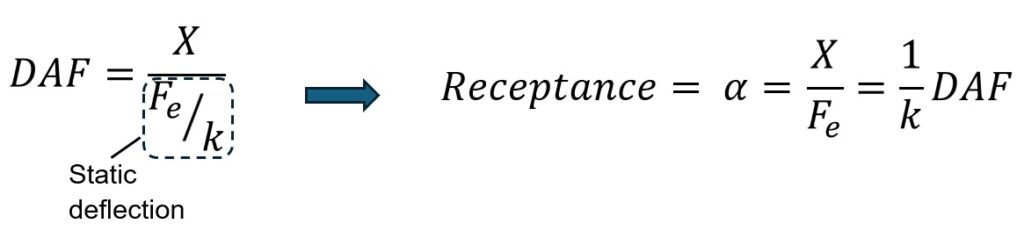
Similarly, we can deduce the ratio between the amplitude of the harmonic displacement X and the amplitude of the external force Fe. This quantity is called receptance, or compliance, and is clearly the inverse of a dynamic stiffness. Its mathematical expression is practically analogous to that of the DAF, as shown here on the side.
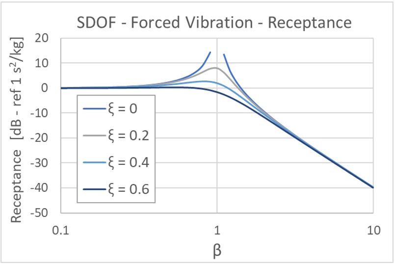
At low frequency ratios (β<<1) the response approaches a constant value proportional to the inverse of stiffness. In this frequency range the spring governs the motion.
At resonance (β≈1) the receptance peak is controlled by damping.
At high frequency ratios (β>>1) receptance drops off rapidly at a rate proportional to 1/𝜔2; this corresponds to a slope of -40 dB/decade. In this frequency range mass governs the motion.
Receptance is the “displacement-based” member of the Frequency Response Function family. You can derive the others by multiplying by 𝜔 as explained below.
The inverse of receptance, that is the ratio of the exciting force Fe to the displacement amplitude X of the suspended mass, is defined as the ‘Dynamic Stiffness’.
In Vibration Mechanics, however, it is common to treat the response of an oscillating system in terms of velocity or acceleration amplitudes, since displacement amplitudes are often too small.
For harmonic excitation, displacement, velocity, and acceleration responses are sinusoidal and linked by angular frequency. The amplitudes are interchangeable through ω and ω² scaling relationships.
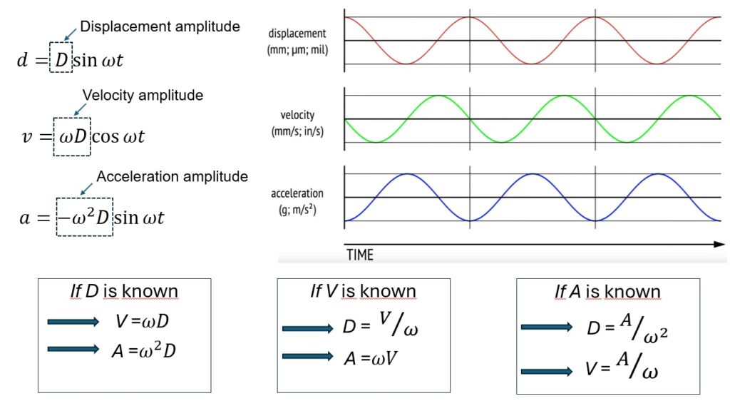
To obtain the ratio between the amplitude of the velocity of the oscillating mass V and the amplitude of the exciting force Fe, it will therefore be sufficient to simply multiply the receptance expression by 𝜔:
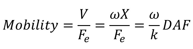
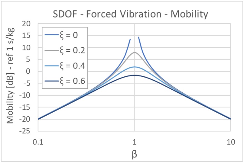
The ratio of velocity to exciting force is called mobility. Intuitively, the greater the mobility of a system, the greater its propensity to vibrate. Mobility of an SDOF system as the damping varies is shown in the diagram here on the side.
At very low frequencies, the mobility is directly proportional to the exciting frequency, therefore to 𝜔. In a logarithmic plot, this corresponds to a slope of +20 dB/decade. The system is stiffness-controlled (controlled by the stiffness, k). The displacement is nearly constant, so the velocity increases linearly with frequency.
At very high frequencies, the mobility is inversely proportional to 𝜔. In a logarithmic plot, this corresponds to a slope of -20 dB/decade. The system is mass-controlled (controlled by the mass, 𝑚). The inertia of the mass prevents the system from rapidly following the force.
Mobility is the central member of the FRF family. The inverse of mobility is known as ‘Mechanical Impedance’.
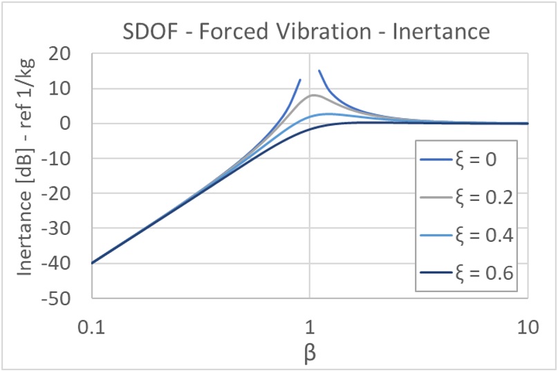
This reasoning can be repeated to find the ratio between the amplitude of the acceleration A of the suspended mass and the amplitude of the exciting force Fe. It will be sufficient to multiply the mobility by the angular frequency 𝜔.
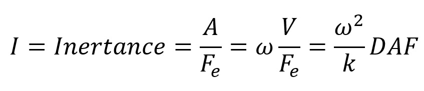
When plotted on a log-log scale (Magnitude vs. Frequency), the slopes of the inertance reveal which physical property dominates the system’s behavior. At low frequencies, the inertance is proportional to 𝜔2/k ; this explains the slope of 40 dB/decade.
At high frequencies, the inertance is proportional to the inverse of mass, that is 1/m. This explains the horizontal asymptote.
Inertance completes the picture of frequency response functions for an SDOF system. The inverse of inertance, that is the ratio of the exciting force Fe to the acceleration amplitude A of the suspended mass, is defined as the ‘Dynamic Mass’.