
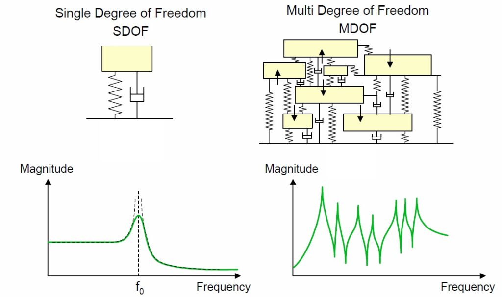
Previous posts have presented the fundamental concepts of Vibration Mechanics for a SDOF system. In reality, however, structures subject to vibrations possess many, theoretically infinite, degrees of freedom. Let’s see how the previous concepts can be extended to more complex systems.
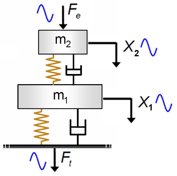
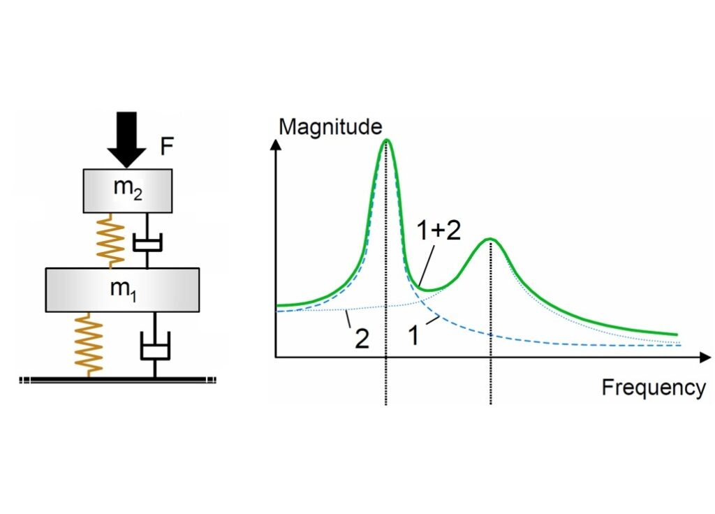
A slightly more complex system than a simple SDOF system consists of two superimposed masses, constrained to vibrate only in the vertical direction. This is a schematic of a double suspension, widely used in practice. This system has two degrees of freedom, rather than just one, and therefore has two natural frequencies at which it can oscillate freely.
If the upper mass is subjected to a harmonic force of known amplitude Fe and frequency f, both masses will oscillate harmonically at steady state. The force transmitted to the foundation Ft will also be harmonic. If we adopt the same definition of force transmissibility T used for the SDOF system, i.e., the ratio of the amplitude of the transmitted force Ft to the amplitude of the exciting force Fe, this time the T diagram will no longer have a single peak, but two, one for each of the potential resonances.
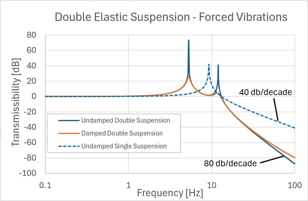
Having accepted this drawback, this solution nevertheless has the notable advantage, compared to the single suspension, of having a transmissibility that decreases much more rapidly at high frequencies, i.e. 80 dB/decade
The graph below shows the transmissibility of a double suspension with and without damping. The dotted line indicates the transmissibility of an undamped SDOF system. The advantage of a double suspension at high frequencies is clear. It is interesting to note that the presence of damping does not shift the resonant frequencies but only limits the transmissibility peaks.
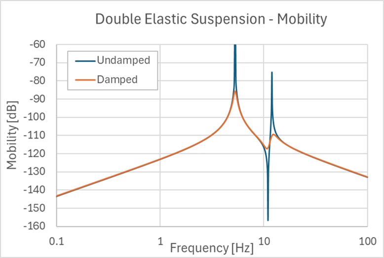
The mobility of a double suspension, with and without damping, is shown in the following graph; here too, the two peaks due to the two resonances are clearly visible. Far from these, the mobility shows the same trends already seen for the SDOF system with slopes of ±20 dB/decade.
It is important to note that the transmissibility and mobility diagrams for a double suspension can be imagined as the result of the superposition of two SDOF systems, with the resonances coinciding with those of the double suspension. This is qualitatively demonstrated in the following image.
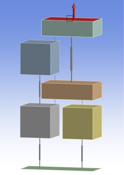
The concepts of transmissibility and mobility can be extrapolated to increasingly complicated discrete systems, such as the one shown here, consisting of five masses, all constrained to move only vertically. The system has five degrees of freedom and therefore five natural frequencies and corresponding natural modes of vibration.
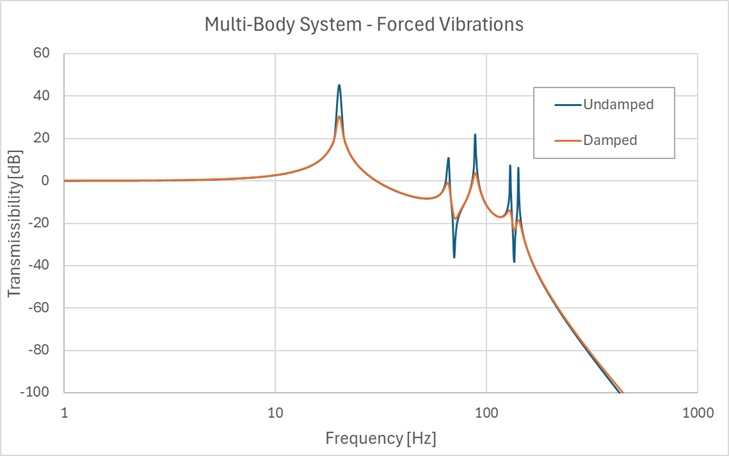
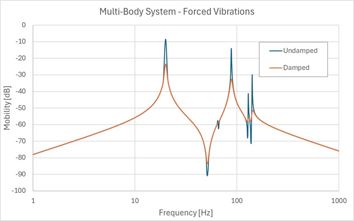
If we subject this system to forced vibrations, with a vertical harmonic force applied to the upper mass, we can also obtain the behavior of transmissibility and mobility, represented in the two following diagrams: the curves without damping are in blue, and the curves with damping are in orange. Again, we can see how the presence of damping does not alter the position of the resonances; only the amplitude of the peak is reduced.
Note how the transmissibility, once the five resonance peaks are passed by, at high frequencies drops with a slope greater than 100 dB/decade in the absence of damping.
In a previous post it was highlighted that for an SDOF system the transmissibility function is the same, both in the case in which a harmonic force is applied to the upper mass and one wishes to determine the force transmitted to the foundation, and in the case in which the foundation is excited to move harmonically and one wishes to determine the harmonic displacement of the suspended mass. This equivalence continues to be valid even for a system with multiple degrees of freedom such as those analyzed in this post.
Since mobility is the ratio between a velocity and a force, in the case of a system with multiple masses constrained to move in a single direction, it is necessary to specify at which points the force acts and at which point the velocity is measured.
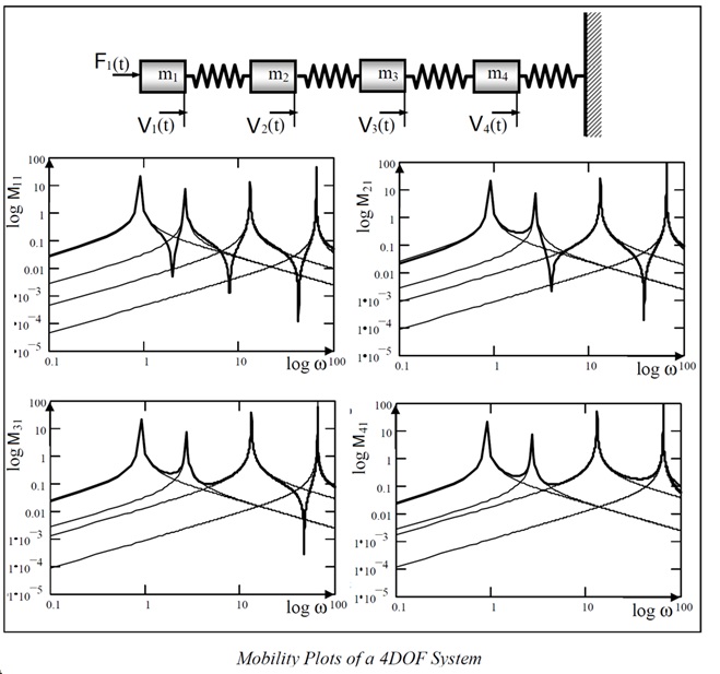
If the two points coincide, we speak of direct mobility. If the points are different, we speak of transfer mobility. In the figure, we see the case of four masses, with the force applied to mass 1, and the velocities measured on all the masses, from which the four mobility diagrams below derive.
In reality, things are even more complicated because force and velocity must also refer to a direction. Therefore, in general, it is also necessary to specify the direction in which the force and velocity act.
The important thing to note is how, even in this case, each mobility diagram of these four masses can be interpreted as the superposition of 4 diagrams of SDOF systems, each with its own resonance.
Previous posts have presented the fundamental concepts of Vibration Mechanics for a SDOF system. In reality, however, structures subject to vibrations possess many, theoretically infinite, degrees of freedom. Let’s see how the previous concepts can be extended to more complex systems.
A slightly more complex system than a simple SDOF system consists of two superimposed masses, constrained to vibrate only in the vertical direction. This is a schematic of a double suspension, widely used in practice. This system has two degrees of freedom, rather than just one, and therefore has two natural frequencies at which it can oscillate freely.
If the upper mass is subjected to a harmonic force of known amplitude Fe and frequency f, both masses will oscillate harmonically at steady state. The force transmitted to the foundation Ft will also be harmonic. If we adopt the same definition of force transmissibility T used for the SDOF system, i.e., the ratio of the amplitude of the transmitted force Ft to the amplitude of the exciting force Fe, this time the T diagram will no longer have a single peak, but two, one for each of the potential resonances.
Having accepted this drawback, this solution nevertheless has the notable advantage, compared to the single suspension, of having a transmissibility that decreases much more rapidly at high frequencies, i.e. 80 dB/decade
The graph below shows the transmissibility of a double suspension with and without damping. The dotted line indicates the transmissibility of an undamped SDOF system. The advantage of a double suspension at high frequencies is clear. It is interesting to note that the presence of damping does not shift the resonant frequencies but only limits the transmissibility peaks.
The mobility of a double suspension, with and without damping, is shown in the following graph; here too, the two peaks due to the two resonances are clearly visible. Far from these, the mobility shows the same trends already seen for the SDOF system with slopes of ±20 dB/decade.
It is important to note that the transmissibility and mobility diagrams for a double suspension can be imagined as the result of the superposition of two SDOF systems, with the resonances coinciding with those of the double suspension. This is qualitatively demonstrated in the following image.
The concepts of transmissibility and mobility can be extrapolated to increasingly complicated discrete systems, such as the one shown here, consisting of five masses, all constrained to move only vertically. The system has five degrees of freedom and therefore five natural frequencies and corresponding natural modes of vibration.
If we subject this system to forced vibrations, with a vertical harmonic force applied to the upper mass, we can also obtain the behavior of transmissibility and mobility, represented in the two following diagrams: the curves without damping are in blue, and the curves with damping are in orange. Again, we can see how the presence of damping does not alter the position of the resonances; only the amplitude of the peak is reduced.
Note how the transmissibility, once the five resonance peaks are passed by, at high frequencies drops with a slope greater than 100 dB/decade in the absence of damping.
In a previous post it was highlighted that for an SDOF system the transmissibility function is the same, both in the case in which a harmonic force is applied to the upper mass and one wishes to determine the force transmitted to the foundation, and in the case in which the foundation is excited to move harmonically and one wishes to determine the harmonic displacement of the suspended mass. This equivalence continues to be valid even for a system with multiple degrees of freedom such as those analyzed in this post.
Since mobility is the ratio between a velocity and a force, in the case of a system with multiple masses constrained to move in a single direction, it is necessary to specify at which points the force acts and at which point the velocity is measured.
If the two points coincide, we speak of direct mobility. If the points are different, we speak of transfer mobility. In the figure, we see the case of four masses, with the force applied to mass 1, and the velocities measured on all the masses, from which the four mobility diagrams below derive.
In reality, things are even more complicated because force and velocity must also refer to a direction. Therefore, in general, it is also necessary to specify the direction in which the force and velocity act.
The important thing to note is how, even in this case, each mobility diagram of these four masses can be interpreted as the superposition of 4 diagrams of SDOF systems, each with its own resonance.